Article No. 8
Design specifications for CWT (Article, Int. Symposium on Cable Dynamics, Paris 2009, pdf-format). Poster to the above article (pdf-format)
Background
The newly proposed Femern fixed link between Denmark and Germany will push the limits in engineering design. The selection of a cable-stayed or suspension bridge will lead to one of the longest bridges of its type in the world. The challenges of designing a bridge are many and the prospects of cable vibrations already preoccupy both the owners and designers. In this connection, the Danish owners/operators Femern Bælt A/S, together with Storebælt A/S, are funding a collaborative research project to examine the ways of reducing the risk of cable vibrations on a bridge solution. A novel climatic wind tunnel facility, dedicated to the testing of structural cables, is being developed as part of this research project.
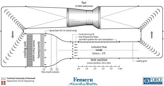
Principle sketch of the Closed-circuit Climatic Wind Tunnel including main features.
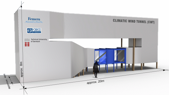
Rendering of the Climatic Wind Tunnel after covering the tunnel structure for thermal insulation and noise reduction.
CONSTRUCTION PROGRESS UPDATE:
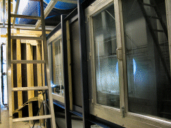
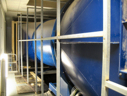
Almost completed tests section (2009-10-08). Framing to case upper flow return (2009-10-22).
Design Concept
Wind-tunnel testing of cables needs to be undertaken at appropriate Reynolds numbers and preferably at full scale, as certain forms of wind-induced vibration are highly dependant on this number and on the correct formation of rain or ice. Smaller low-speed wind-tunnels are often unable to achieve the necessary Reynolds numbers without significant levels of blockage. Apart from wind-tunnel blockage, the physics of ice accumulation including thermodynamic effects and rivulet establishment for rain conditions are significantly biased at reduced scale. As several of the most dominant wind-induced vibrations occur within the subcritical and critical Reynolds number regions , it is desirable that a wind-tunnel test facility should be able to test up to at least the supercritical range.
Sectional cut through wind tunnel at test section.
Additonally, a suitable wind-tunnel test facility will be able to test cables for varying wind angles-of-attack. An examination of the existing cable-stayed bridges reveals that bridge cables with angles of inclination of less than 22.5deg would start to become structurally inefficient. Consequently, a test section of 2m height would result in a section length of approximately 5m.
Side view on test section.
A closed-circuit type was chosen especially with respect to control air temperature at any time for simulating the relevant climatic conditions. All components of the wind tunnel have been optimised to reduced the induced pressure loss. The size of the wind tunnel is a compromise of aerodynamic design necessity and available space. To house the facility major reconstruction work was required as well as an expansion of the power supply relais station of FORCE Technology's testing facility.
Specification
The design specification listed below are based on the research requirements discussed above. In spring 2010 first results will be available with detailed information on the achieved flow and climatic test conditions.
| Property/dimension |
Value |
| Test section inner cross-section |
2.0 x 2.0m |
| Test section length |
5.0m |
| Maximum airspeed in turbulent flow |
25m/s |
| Minimum turbulence intensity Iu |
1% to 20% |
| Cloud air vapor density |
0.4g/m^3 |
| Droplet size |
10 to 50µm |
| Minimum air temperature at max. speed |
-5degC |